Undercuts in Plastic, 3a of 3.
It felt like cheating, but I did it anyway.
ENGINEERING AND DESIGN STUFFPLASTIC PART DESIGN
Bert
10/24/20233 min read


This is post 3a of a series of 3 posts on undercuts. (3a? Yeah, so, I added to the list. Sue me.) Here are part 1 and part 2.
Twenty some years ago on a Friday afternoon when CAD databases had to be out by the end of the day, one of the engineers on my team told me that he found some undercuts in a part when he did a draft check. Oh, shitake mushrooms, I thought. The undercut was due to the shape of the product and the irregular way that the parts were split. We needed a solution pronto or our customer would not be pleased. After looking at it for a little while, I came up with a solution that kind of looked like and felt like cheating but it worked and no one would know after the product was assembled, so we did it.
What was this rabbit I pulled out of my sleeve? I am happy to share but you need to know a little about the part. First, this is the actual finished product, showing the areas that had the undercut.
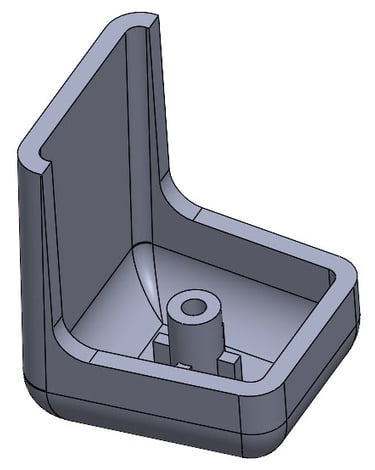
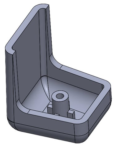
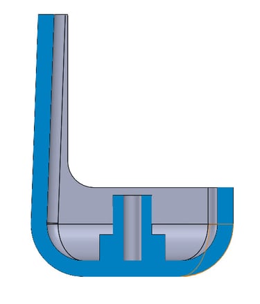
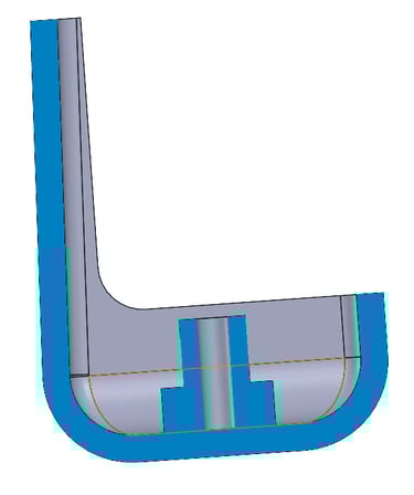
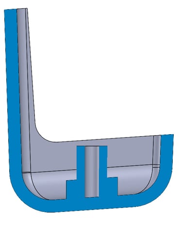
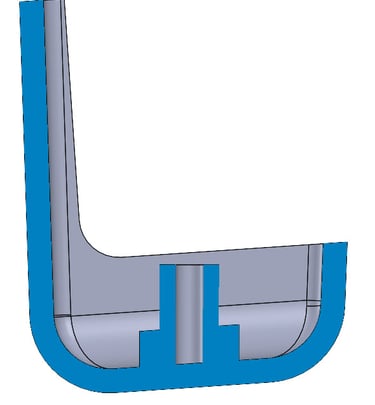
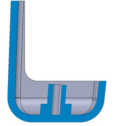
Below are pictures of a simplified version of the rear piece and its cross section. The boss in the middle is for positioning a compression spring, so its details were not super critical.
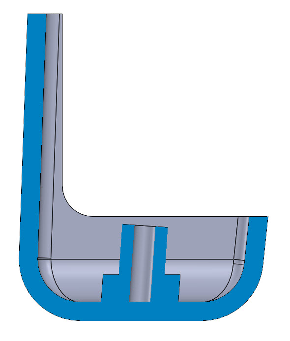
Before you accuse us of just moving the problem, we also changed the draft on the spring boss in the middle and on the short side of the part. That made the spring boss look like the Leaning Tower of Pisa from the perspective of the part in use, but, it was straight and tall with respect to the mold parting line. I have to admit I was quite pleased and relieved with that solution.
“Tilting” the part so the parting line is not perpendicular to how the part is used is something I have done a handful of times of the years, so it is a good concept to keep in your designer bag of tricks.
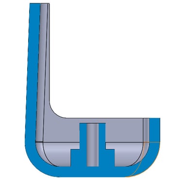
So how did we get rid of that undercut without redoing the outside surface of the entire part and thus affect multiple parts? We decided that the part would be tilted in the mold, so it would look like the the image below.